

Why Does Your CT Clamp Show Negative Readings and How Can You Fix It?
CT clamp polarity negative readings occur when the current transformer clamp is installed backwards or when the conductor passes through the clamp in the opposite direction from the intended polarity marking. The key takeaway is that negative readings are not equipment failures—they indicate a polarity mismatch that requires physical repositioning of the clamp or reversal of the conductor path. When a CT clamp reads negative, it means the magnetic field direction through the clamp core is reversed relative to the clamp’s internal coil orientation, causing the secondary output to invert. This is a common issue in electrical monitoring systems, energy management setups, and smart home power measurement installations. Understanding CT clamp polarity is essential for accurate energy consumption tracking, demand response systems, and real-time power monitoring. The accuracy of your readings depends entirely on correct polarity alignment, as even a properly calibrated clamp will produce inverted values if installed backwards. In April 2026, as more homeowners and businesses adopt advanced energy monitoring solutions, recognizing and correcting polarity issues has become a critical skill for installers and technicians.
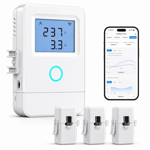
Nestool WiFi Home Energy Monitor with 3 80A CT Clamps
- 【Panel-Level Energy Monitoring】Designed for selected circuit monitoring in your electrical panel. Track high-power home circuits such as HVAC/AC, water heater, laundry, garage equipment, solar-related circuits, or other dedicated appliances. Supports AC 100–240V input voltage. Installation involves electrical wiring; Installation by a qualified electrician is recommended if you are not familiar with electrical panel wiring.
- 【3 CT Clamps Included】Monitor up to 3 selected circuits at the same time with 3 CT clamps. Easily compare major energy loads and identify which appliances or areas use the most electricity, helping you better understand where your home energy is being used.
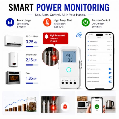
- 【Smart Life/Tuya App Tracking】Connect through 2.4GHz WiFi and view voltage, current, power, and energy consumption from your phone. Switch between Channel A/B/C for real-time monitoring of selected circuits anytime through the Smart Life or Tuya App.
- 【Historical Energy Data】Review usage trends over time to better understand daily and long-term electricity consumption. Great for home energy management, workshops, rental units, small businesses, and selected solar-related circuit monitoring.
- 【High Temp Alert & Remote Control】Connect the external temperature sensor to monitor temperature and receive app alerts when it exceeds 50°C, helping you stay aware of abnormal high-temperature conditions. Remote ON/OFF control is supported for one connected circuit, with relay control up to 15A.



As an Amazon Associate we earn from qualifying purchases. Product prices and availability are accurate as of the date/time indicated.

Current transformer clamps are fundamental components in electrical measurement systems. They work by detecting the magnetic field generated by current flowing through a conductor, then converting that field into a proportional secondary current or voltage signal. When polarity is correct, the clamp’s internal coil aligns with the conductor’s current direction, producing positive readings that accurately represent power flow. However, installation errors, unclear polarity markings, or conductor routing mistakes frequently result in reversed polarity, manifesting as negative values on meters or monitoring systems. This issue becomes particularly problematic in smart home energy management systems where negative readings can confuse automation logic or prevent accurate billing calculations. Understanding the root causes and solutions ensures reliable energy monitoring and prevents costly measurement errors.
What Causes CT Clamp Polarity to Produce Negative Readings?
CT clamp polarity negative readings stem from several specific installation and operational factors. The primary cause is physical reversal of the clamp orientation—installing the clamp backwards on the conductor so the marked polarity direction opposes the actual current flow. Most CT clamps feature directional arrows or polarity markings (often labeled as dot/polarity indicators on the clamp body) that indicate the correct orientation relative to current direction. When the clamp is rotated 180 degrees, the secondary output inverts, producing negative readings on any connected meter or monitoring device.
A second common cause involves conductor routing through the clamp. If the conductor enters the clamp from the opposite end than intended by the manufacturer’s polarity design, negative readings result. This frequently occurs in retrofit installations where existing electrical infrastructure must be adapted to accommodate new monitoring equipment. Technicians may accidentally route the conductor through the clamp in reverse, especially in cramped electrical panels where space constraints limit positioning options.
Incorrect secondary wiring connections represent a third cause. If the secondary leads from the CT clamp are reversed at the meter or monitoring device input terminals, the polarity inverts. This can happen during initial installation or after maintenance when technicians reconnect secondary wires without verifying polarity continuity. Additionally, some measurement systems use software-configurable polarity settings that may be incorrectly configured, creating apparent negative readings even when hardware is properly installed.
Environmental factors and electromagnetic interference can also affect polarity accuracy. External magnetic fields from nearby power lines or equipment can distort the CT clamp’s magnetic field detection, though this typically causes measurement errors rather than consistent negative readings. Temperature variations and conductor movement within the clamp can also impact accuracy, particularly in older or worn clamps where internal components have degraded.
How Do You Diagnose and Verify CT Clamp Polarity Accuracy?
Diagnosing CT clamp polarity issues requires systematic testing using proper electrical measurement tools and procedures. The most straightforward diagnostic method involves visual inspection of polarity markings and physical orientation verification. Examine the CT clamp body for manufacturer markings—typically arrows, dots, or alphanumeric labels indicating correct installation direction. Compare these markings against the actual conductor path through the clamp. If the conductor enters from the opposite side of the marked direction, polarity reversal is confirmed.

For more precise diagnosis, use a multimeter or clamp meter to measure secondary voltage output. With the clamp properly connected to a test load (or monitored in an operational circuit), measure the secondary terminals. If you observe negative voltage readings on a properly functioning clamp meter, polarity is reversed. Alternatively, temporarily reverse the secondary connections at the meter input—if readings change from negative to positive, the clamp hardware is correct but secondary wiring is reversed.
Advanced diagnostic testing involves using a calibrated clamp meter or power quality analyzer to measure current direction and phase relationships. These instruments can definitively establish whether current flows in the direction the CT clamp expects. Power quality analyzers provide detailed polarity information and can log readings over time, revealing intermittent polarity issues that simple multimeter testing might miss.
Documentation review is equally important. Consult the CT clamp manufacturer’s installation manual for specific polarity markings and orientation requirements. Different clamp models use varying conventions—some use arrow markings, others use colored leads or numbered terminals. Misinterpreting these conventions causes polarity errors. Create a detailed installation diagram showing clamp orientation, conductor routing, and secondary wire connections. This documentation aids troubleshooting and prevents repeated errors during maintenance or system upgrades.
What Are the Best Practices for Correct CT Clamp Installation and Polarity Alignment?
Proper CT clamp installation begins with thorough pre-installation planning and conductor assessment. Before physically installing any clamp, trace the conductor path from source to load, identifying the direction of current flow under normal operating conditions. Most electrical systems have conventional current flow direction (positive to negative), which guides polarity orientation. Mark the conductor with tape or labels indicating the correct direction, then position the CT clamp so its polarity marking aligns with this flow direction.

When installing the clamp, ensure the conductor passes completely through the clamp opening, not around the outside edge. Partial conductor insertion or positioning the conductor off-center within the clamp reduces measurement accuracy and can introduce phase errors. The conductor should sit centered in the clamp’s magnetic core window. For three-phase systems, install separate CT clamps on each phase conductor, maintaining consistent polarity orientation across all three clamps. This ensures balanced three-phase power measurements and prevents calculated power errors.
Secondary wiring requires equal attention to polarity. Most CT clamps feature marked secondary terminals—typically labeled P1/P2 or S1/S2—indicating polarity. Connect the primary secondary terminal (P1 or S1) to the corresponding input on your meter or monitoring device, and the secondary terminal (P2 or S2) to the return or ground input. Use color-coded wires (typically red for positive polarity, black for negative) to maintain clarity and prevent connection errors during troubleshooting.
Test every installation before placing it into service. Use a multimeter or clamp meter to verify that readings are positive when current flows in the expected direction. If negative readings appear, immediately halt operation and correct the polarity before resuming monitoring. Document all polarity verification tests and create a permanent record showing correct orientation and secondary wire connections. This documentation proves invaluable for future maintenance, system upgrades, or troubleshooting by other technicians.
For smart home energy monitoring systems and automated power management setups, consider using CT clamps with integrated polarity indicators or digital displays that show reading direction. These advanced clamps reduce installation errors and provide immediate visual confirmation of correct polarity. Additionally, select monitoring software or devices that allow polarity correction through configuration settings—if a clamp is accidentally installed backwards, software-based polarity reversal can correct readings without physical reinstallation.
How Do You Correct Negative CT Clamp Readings Once They Occur?
Correcting negative CT clamp readings depends on the root cause identified during diagnosis. If the clamp itself is installed backwards, the simplest solution is physical reversal. Remove the clamp from the conductor, rotate it 180 degrees, and reinstall it so the polarity marking aligns correctly with current flow direction. This typically requires de-energizing the circuit or using safe isolation procedures, depending on your facility’s electrical safety protocols. After reinstallation, immediately verify that readings return to positive values using a multimeter or clamp meter.

If the conductor routing is reversed (passing through the clamp from the wrong direction), you may need to reroute the conductor or install an additional clamp on a different section of the circuit where routing can be corrected. In some cases, particularly in existing installations with space constraints, rerouting may be impractical. In these situations, implementing software-based polarity correction becomes the preferred solution—configure your monitoring device or software to invert the clamp’s readings, mathematically reversing the negative values to positive.
When secondary wiring connections are reversed, simply swap the two secondary leads at the meter or monitoring device input terminals. Reverse the red and black wires (or P1 and P2 connections) so they align with correct polarity. This is often the quickest correction method and requires no physical manipulation of the clamp itself. Always verify the correction by taking new readings immediately after making wire changes.
For systems with software-configurable polarity, access the monitoring device’s settings menu and locate polarity or phase angle configuration options. Select the option to reverse or invert the polarity for the affected clamp. Save the settings and verify that readings now display as positive. This method is particularly valuable in complex multi-clamp systems where multiple channels may have polarity issues—you can correct each channel individually through software configuration.
After implementing any correction, monitor the system for 24-48 hours to ensure readings remain positive and stable. Check that power calculations, energy totals, and demand measurements align with expected values based on circuit load. If readings remain negative or become erratic after correction, investigate for secondary causes such as electromagnetic interference, equipment malfunction, or incorrect measurement ranges on your monitoring device.
Why Is CT Clamp Polarity Accuracy Critical for Energy Monitoring Systems?
CT clamp polarity accuracy directly impacts the reliability and usefulness of energy monitoring data. In commercial buildings and industrial facilities, negative readings from reversed polarity clamps corrupt energy consumption records, preventing accurate billing and cost analysis. If a monitoring system reports negative power values due to polarity errors, facility managers cannot determine actual energy usage, making it impossible to identify efficiency opportunities or verify utility bills. This becomes particularly problematic in demand response programs where accurate real-time power measurement is essential for participation and compensation.
For smart home energy management systems, polarity errors create cascading problems. If a home energy monitoring system receives negative readings from a CT clamp measuring solar panel output or battery discharge, automation logic may malfunction. A home automation system might fail to activate energy-saving features, incorrectly calculate net metering credits, or misroute power between sources. In homes with backup power systems or microgrids, polarity errors can prevent proper load balancing and create safety hazards by allowing power to flow in unexpected directions.
Three-phase power systems are particularly sensitive to polarity errors. If CT clamps on different phases have inconsistent polarity (some correct, some reversed), the monitoring system calculates incorrect phase angles, reactive power values, and power factor measurements. This leads to inaccurate power quality analysis and can trigger false alarms for power factor correction systems. In industrial settings, these errors can prevent early detection of electrical problems that could escalate into equipment damage or safety incidents.
Regulatory compliance and auditing also depend on accurate polarity. Utility companies, building certifications (such as LEED or Energy Star), and regulatory agencies require verified energy consumption data. Negative readings or polarity errors during audits raise questions about data integrity and can result in failed certifications or disputed billing. Maintaining accurate polarity ensures your monitoring system passes audits and provides defensible data for regulatory submissions.
What Common Mistakes Should You Avoid When Installing CT Clamps?
One of the most frequent installation mistakes is ignoring or misinterpreting manufacturer polarity markings. Technicians sometimes install clamps without consulting the instruction manual, assuming all CT clamps follow the same polarity convention. Different manufacturers use different marking systems—some use arrows, others use colored dots or numbered terminals. Failing to verify the specific convention for your clamp model inevitably leads to polarity errors. Always consult the manufacturer’s documentation before installation and cross-reference the markings on your specific clamp.
Improper conductor positioning within the clamp creates another common error. Placing the conductor off-center or allowing it to touch the clamp’s magnetic core reduces measurement accuracy and can introduce phase errors. The conductor must sit centered in the clamp’s window opening, with equal spacing on all sides. In cramped electrical panels, technicians sometimes position conductors at angles or partially outside the clamp opening to fit space constraints. This severely degrades measurement accuracy and should be avoided—if space is insufficient, consider using a smaller clamp model or rerouting conductors to create adequate space.
Failing to test installations before placing them into service is a critical mistake. Many technicians install clamps and immediately begin relying on the data without verifying polarity or measurement accuracy. Simple multimeter testing takes only minutes but catches polarity errors before they corrupt monitoring data. Establish a mandatory testing protocol requiring verification of positive readings and reasonable measurement ranges before any CT clamp enters service.
Mixing clamp types or specifications in multi-clamp systems creates consistency problems. If you install different CT clamp models with different turns ratios or polarity conventions on the same system, readings become inconsistent and difficult to interpret. Select a single clamp model for all measurements in a given system, ensuring uniform polarity conventions and measurement characteristics. This simplifies installation, troubleshooting, and future maintenance.
Inadequate secondary wiring protection and documentation causes problems during troubleshooting. Secondary wires from CT clamps should be routed in conduit or cable trays, protected from physical damage and electromagnetic interference. Unmarked or poorly documented secondary connections make it nearly impossible to identify polarity issues during troubleshooting—you cannot determine which terminal is P1 or P2 without clear labeling. Implement a comprehensive labeling system and maintain detailed installation diagrams showing all secondary connections.
Recommended Products

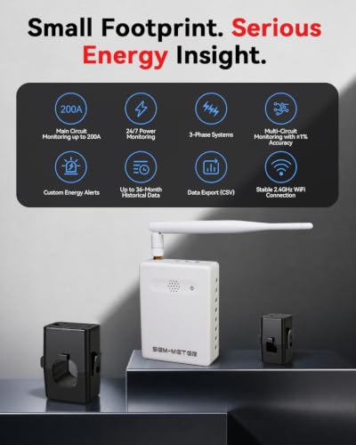
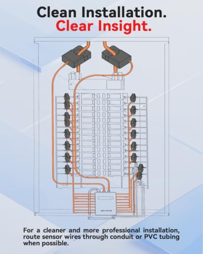
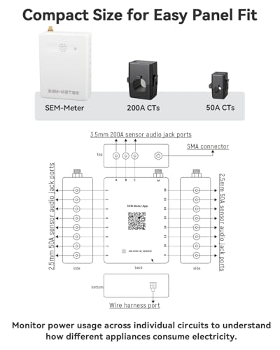
16-Circuit Energy Monitor with Real-Time Tracking & Cost Analysis
- ⚡ EASY INSTALLATION: Installs in circuit panel of most homes with clamp-on sensors. Supports single-phase up to 240VAC line-neutral; single, split-phase 120/240VAC; and three-phase up to 415Y/240VAC (no Delta). The branch lines can automatically match different phases and have no restrictions in terms of quantity and voltage.Panels with access only to busbars will need flexible sensors available from SEM-Meter.
- ⚡ ENERGY MONITORING ANYTIME, ANYWHERE: Monitor your home's real power anywhere, anytime to prevent costly repairs, conserve energy, and save costs. Monitor solar / net metering. Light commercial 3 phase option available as a separate bundle. Protected by a 1-year warranty.
- ⚡ VARIOUS ELECTRICAL APPLIANCE MONITORING: Comes with 16 50A sensors to accurately monitor your air conditioner, furnace, water heater, washer, dryer, range, etc.
- ⚡ LOWER YOUR ELECTRIC BILL: SEM-Meter measures real-time spending and gets actionable notifications to understand where savings can be made, both to lower your electric bill and to conserve energy and protect the planet’s resources. Be an environmentalist.
- ⚡ REAL-TIME ENERGY DATA: Connect SEM-Meter device via 2.4GHz WiFi to monitor energy usage, with an accuracy range of 1%. View usage in real time through Android/Apple software. Statistics of power usage in now/day/week/month/year format: the validity period of hourly exported data is 90 days, and the exported data of day/month/year data is permanent, available at any time Export from application.
- ⚡ Super Privacy Mode ! run without our cloud ,without our app!! use your own MQTT server only!! run in LAN without internet access !!! (HomeAssistant with MQTT required.)
- ⚡ SMART ELECTRICITY BILL ALLOCATION FOR RENTAL HOMES: Perfect for rental houses, shared apartments, and multi-room properties. With multiple circuit monitoring, you can track power usage for each bedroom, common area, or EV charger without installing multiple electricity meters. Supports customizable electricity rate templates including peak, off-peak, and holiday pricing, allowing automatic electricity cost calculation based on time-of-use tariffs. After setting the pricing template, users can clearly see electricity usage and cost for each room or circuit, making billing transparent and helping landlords or property managers manage fair electricity allocation.


As an Amazon Associate we earn from qualifying purchases. Product prices and availability are accurate as of the date/time indicated.
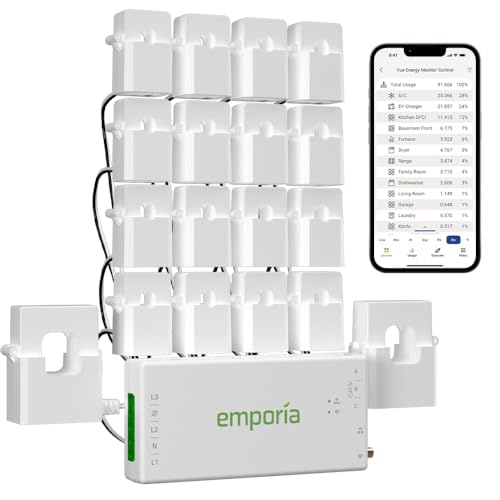
Emporia Vue 3 Home Energy Monitor with 16 Circuit Sensors
- SAFETY YOU CAN TRUST WITH UL CERTIFICATION: With Emporia Energy, your home energy monitoring is safe, reliable, and certified. The Emporia Vue is UL Listed, meaning it has met rigorous safety standards for electrical products in the U.S. and Canada. This certification ensures that every component has been thoroughly tested to prevent hazards, such as overheating, short-circuiting, or fire, offering you peace of mind as you manage your home’s energy consumption.
- INSTALLS IN CIRCUIT PANEL of most homes with clamp-on sensors. Supports Single phase, Single-split phase, and 2-wire systems. 3-wire systems; 3-phase, 4-wire Wye systems with earthed (TN or TT) neutral (no-Delta) are supported with an additional 200A sensor (sold separately).
- 24/7 ENERGY MANAGEMENT AND MONITORING: Automate, manage and control your home's real power anywhere, anytime to prevent costly repairs, conserve energy, and save costs. Monitor solar / net metering. PROTECTED BY A 1-YEAR WARRANTY.
- LOWER YOUR ELECTRIC BILL: Configure settings in the Emporia Energy App to automate energy management for time of use, peak demand, excess solar, and rewards programs. You can even see live reporting and invaluable savings opportunities instantly. Gauge real-time spending and get actionable notifications and automated energy management to help you reduce costs.
- REAL-TIME ENERGY DATA: REQUIRES 2.4 GHz WIFI WITH AN INTERNET CONNECTION to monitor energy use with iPhone / Android / Web app. Vue sensors collect energy data and are accurate from ±2%. The Vue is UL and CE Listed for your safety. 1 second data is only available in the app (when actively open) and retained 3 hours. Minute and hour data are retained in the cloud. 1 minute data is retained 7 days, 1 hour data is retained indefinitely. Export cloud data whenever you want in the app.
- APPLIANCE MONITORING WITHOUT GUESSWORK: Comes with sixteen branch (50A) sensors to accurately monitor your critical loads like air conditioner, furnace, water heater, washer, dryer, range, etc. New and improved screw terminals / ports allow CT wires to be trimmed to reduce panel clutter.


As an Amazon Associate we earn from qualifying purchases. Product prices and availability are accurate as of the date/time indicated.
Frequently Asked Questions
What does a negative CT clamp reading actually mean?
A negative CT clamp reading indicates the clamp’s polarity is reversed relative to current flow direction. This means the magnetic field through the clamp is opposite to what the clamp’s internal coil expects, inverting the secondary output. Negative readings are not equipment failures—they signal an installation error requiring polarity correction through physical reversal or secondary wire swapping.
Can you fix a negative reading without removing the CT clamp?
Yes, if the clamp hardware is correctly installed but secondary wires are reversed, you can swap the two secondary lead connections at the meter input terminals to fix negative readings. Additionally, many monitoring systems allow software-based polarity inversion through configuration settings, mathematically reversing readings without physical changes to the clamp installation.
How do you know which way the CT clamp should face?
Consult the manufacturer’s installation manual for specific polarity markings on your clamp model. Most clamps feature arrows, colored dots, or numbered terminals (P1/P2) indicating correct orientation. Align these markings with the conductor’s current flow direction—typically from power source toward the load. When in doubt, test with a multimeter before placing the system into service.
Does polarity matter for AC current measurement?
Yes, polarity matters significantly for AC current measurement. While AC current alternates direction, CT clamps measure the direction relative to a reference point. Reversed polarity creates negative readings and causes errors in power calculations, power factor measurements, and three-phase systems. Correct polarity alignment is essential for accurate AC power measurement.
What happens if you ignore negative CT clamp readings?
Ignoring negative readings corrupts your energy monitoring data, making it impossible to accurately track power consumption, calculate costs, or analyze efficiency. In automated systems, negative readings can trigger false alarms or prevent energy-saving features from activating. Always investigate and correct negative readings before relying on monitoring data.
Can environmental factors cause false negative readings?
Environmental factors like electromagnetic interference or temperature extremes can affect measurement accuracy, but they typically cause measurement errors rather than consistent negative readings. True negative readings indicate polarity reversal, not environmental interference. However, environmental factors may worsen accuracy of already-reversed polarity clamps.
Is Correct CT Clamp Polarity Essential for Reliable Energy Monitoring in 2026?
Absolutely. As we move deeper into 2026, energy monitoring has become integral to smart home automation, commercial building management, and industrial operations. The proliferation of smart energy devices, real-time power monitoring, and automated demand response systems means CT clamp accuracy is more critical than ever. A single polarity error can cascade through interconnected systems, affecting home automation decisions, energy billing accuracy, and regulatory compliance.
The good news is that polarity errors are entirely preventable through proper installation practices and thorough testing. By understanding the causes of negative readings, implementing systematic diagnostic procedures, and following best practices for installation and verification, you can ensure your CT clamp measurements remain accurate and reliable. Whether you’re installing energy monitoring for a smart home, upgrading a commercial building system, or maintaining industrial power measurement equipment, correct polarity alignment is non-negotiable.
The investment in proper installation and verification pays dividends through accurate data, reliable automation, and confidence in your energy management decisions. Take time to understand your specific CT clamp model’s polarity requirements, document your installation thoroughly, and test before placing systems into service. If you encounter negative readings, use the diagnostic and correction methods outlined in this guide to quickly identify and resolve the issue. By prioritizing polarity accuracy, you ensure your energy monitoring system provides the reliable, trustworthy data necessary for effective energy management and smart home automation in 2026 and beyond.



Write Your Review
No reviews yet. Be the first to share your experience!